चित्र:Planar core assembly exploded.png
इस पूर्वावलोकन का आकार: 800 × 600 पिक्सेल। दूसरे रेसोल्यूशन्स: 320 × 240 पिक्सेल | 640 × 480 पिक्सेल | 1,024 × 768 पिक्सेल | 1,280 × 960 पिक्सेल।
मूल चित्र ((1,280 × 960 पिक्सेल, फ़ाइल का आकार: 154 KB, MIME प्रकार: image/png))
|
|
यह फ़ाइल विकिमेडिया कॉमन्स से है। वहाँ पर इसका विवरण पृष्ठ निम्नोक्त है। कॉमन्स मुक्त लाइसेंसों के अंतर्गत उपलब्ध मीडिया फ़ाइलों का संग्रह है। आप भी इसमें मदद कर सकते हैं। |

|
This technology image could be re-created using vector graphics as an SVG file. This has several advantages; see Commons:Media for cleanup for more information. If an SVG form of this image is available, please upload it and afterwards replace this template with
{{vector version available|new image name}}.
It is recommended to name the SVG file “Planar core assembly exploded.svg”—then the template Vector version available (or Vva) does not need the new image name parameter. |
सारांश
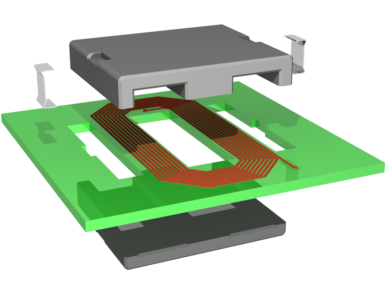
| विवरण | Exploded view of an planar inductor constituted by a spiral track on a printed circuit board and a planar magnetic core |
| दिनांक | |
| स्रोत | अपना कार्य |
| लेखक | Cyril BUTTAY |
| अनुमति (इस चित्र का पुनः उपयोग करना) |
as licensed |
| दूसरे संस्करण | Image:Planar core assembly.png |
इस चित्र का चित्र गुणवत्ता निर्देशों की कसौटी पर मूल्यांकन किया गया है और इसे एक गुणवत्तायुक्त चित्र माना जाता है।
|
लाइसेंस
मैं, इस कार्य का/की कॉपीराइट धारक, इसे निम्न लाइसेंसों के अंतर्गत प्रकाशित करता/करती हूँ:

|
इस दस्तावेज़ को Free Software Foundation द्वारा प्रकाशित GNU मुक्त प्रलेख लाइसेंस के संस्करण 1.2 या नए (बिना किसी अपरिवर्तनीय अनुभागों और अगले या पिछले आवरण के टेक्स्ट के) के अंतर्गत प्रतिलिपि बनाने, बाँटने और/या बदलने की अनुमति प्रदान की जाती है। इस लाइसेंस की एक प्रतिलिपि GNU मुक्त प्रलेख लाइसेंस नामक अनुभाग में शामिल है। |
| इस फ़ाइल को क्रिएटिव कॉमन्स श्रेय-समानसांझा 3.0 अनरिपोर्टेड लाइसेंस के अंतर्गत लाइसेंस किया गया है। | ||
| ||
| This licensing tag was added to this file as part of the GFDL licensing update. |
इस फ़ाइल को क्रिएटिव कॉमन्स श्रेय-समानसांझा 2.5 साधारण, 2.0 साधारण और 1.0 साधारण लाइसेंस के अंतर्गत लाइसेंस किया गया है।
- आप खुलकर:
- बाँट सकते हैं – रचना की प्रतिलिपि बना सकते हैं, बाँँट सकते हैं और संचारित कर सकते हैं
- रीमिक्स कर सकते हैं – कार्य को अनुकूलित कर सकते हैं
- निम्नलिखित शर्तों के अंतर्गत:
- श्रेय – यह अनिवार्य है कि आप यथोचित श्रेय प्रदान करें, लाइसेंस की कड़ी प्रदान करें, और अगर कोई बदलाव हुए हों तो उन्हें इंगित करें। आप ऐसा किसी भी उचित तरीके से कर सकते हैं, लेकिन किसी भी तरह उससे यह नहीं संकेत नहीं किया जाना चाहिए कि लाइसेंसधारी द्वारा आपको अथवा आपके इस प्रयोग का समर्थन किया जा रहा हो।
- समानसांझा – अगर आप इस रचना में कोई बदलाव करते हैं या इसपर आधारित कुछ रचित करते हैं तो आप अपने योगदान को सिर्फ इसी या इसके सामान किसी लाइसेंस के अंतर्गत बाँट सकते हैं।
आप अपना पसंद का लाइसेंस चुन सकते हैं।
Made using povray 3.6 and the following code:
#declare RAD = on;   // use radiosity?
#declare Exploded=on; // exploded view or not?
#declare CoilLength = 2.6;

#include "functions.inc"
#include "metals.inc"
#include "colors.inc"
global_settings {
  #if(RAD)
    radiosity {
      brightness 0.60
      count 100
      error_bound 0.2
      gray_threshold 0.0
      low_error_factor 0.2
      minimum_reuse 0.015
      nearest_count 10
      recursion_limit 1
      #if (version>3.1)
        adc_bailout 0.01
        max_sample -1.0
        media off
        normal off
        always_sample 1
        pretrace_start 0.08
        pretrace_end 0.01
      #end
    }
  #end
}

background { color White }

// declarations for the E magnetic core------------------------------------------------
#declare corner = intersection { // a quarter of cyclindic volume used to "round" the corners
  lathe {
    linear_spline
    6
    <0,0>,<0.05,0>, <0.1,0.05>, <0.1,2.95>,<0.05,3>, <0,3>
    rotate 90*x
  }
  box {<-10,-10,-10>,<10,0,10>}
}

#declare side =  prism { // the extrusions of the volume
  linear_sweep
  linear_spline
  0, 1, 9,
  <0.05,0>, <0,0.05>, <0,2.95>, <0.05,3>, <0.25,3>, <0.3,2.95>, <0.3,0.05>, <0.25,0>, <0.05,0>
}

#declare middle =  prism { // the extrusion of the middle leg
  linear_sweep
  linear_spline
  0, 1, 9,
  <0.05,0>, <0,0.05>, <0,2.95>, <0.05,3>, <0.95,3>, <1,2.95>, <1,0.05>, <0.95,0>, <0.05,0>
}

#declare Ecore = difference {
  union {
    object {side scale <1,3.4,1> rotate -90*z translate <-1.7,0.2,0> }
    object {side scale <1,0.5,1> translate -1.8*x  }
    object {middle scale 0.5*y translate -.5*x  }
    object {side scale <1,0.5,1> translate 1.5*x  }
    object {corner translate -1.7*x}
    object {corner translate 1.7*x}
  }
  union { // the notches where the clips sit
      box {<-10,-10,1.2>,<-1.5,0,1.8>}
      box {<10,-10,1.2>,<1.5,0,1.8>}
  }
  pigment {Gray50}
}

// declarations for the I magnetic core------------------------------------------------
#declare Icore =  difference {
  union {
    object {side scale <1,3.4,1> rotate -90*z translate <-1.7,0.2,0> }
    object {side scale <1,0.2,1> translate -1.8*x  }
    object {middle scale 0.2*y translate -.5*x  }
    object {side scale <1,0.2,1> translate 1.5*x  }
    object {corner translate -1.7*x}
    object {corner translate 1.7*x}
  }
  union { // the notches where the clips sit
      box {<-10,-10,1.2>,<-1.5,0,1.8>}
      box {<10,-10,1.2>,<1.5,0,1.8>}
  }
  pigment {Gray50}
}

//declaration of the coil element-----------------------
#declare coil = union {
  union {
    #declare NbTurns = 8;
    #declare Pitch =0.08; // the distance between two loops
    #declare Xstart =0.6;  // the spiral rolls around the origin
    #declare Zstart =2;
    #declare InitCorner =0.4; // initial length of the 45degree filet
    #declare Index=0;
    #declare Width=0.05;
    #declare DeltaL=Pitch*tan(radians(22.5)); //variation in lenght of the track on each turn
    #while(Index <= NbTurns)
      #declare Lengthcorner=InitCorner+2*Index*DeltaL;
      #declare Xlength=2*(Xstart+Index*DeltaL-InitCorner*cos(radians(45)));
      #declare Zlength=2*(Zstart+Index*DeltaL-InitCorner*cos(radians(45)));
      box{<0,0,0>,<-Width,0.01,-Zlength> translate <Xstart+Index*Pitch,0,Zlength/2>}
      box{<0,0,0>,<-Width,0.01,-Lengthcorner> rotate 45*y translate <Xstart+Index*Pitch,0,-Zlength/2>}
      box{<0,0,0>,<-Xlength,0.01,Width> translate <Xlength/2,0,-Zstart-Index*Pitch>}
      box{<0,0,0>,<-Width,0.01,-Lengthcorner> rotate 135*y translate <-Xlength/2,0,-Zstart-Index*Pitch>}
      box{<0,0,0>,<Width,0.01,Zlength+DeltaL> translate <-Xstart-Index*Pitch,0,-Zlength/2>}
      box{<0,0,0>,<-Width,0.01,-Lengthcorner> rotate 225*y translate <-Xstart-Index*Pitch,0,Zlength/2+DeltaL>}
      box{<0,0,0>,<Xlength+Pitch,0.01,-Width> translate <-Xlength/2,0,+Zstart+Index*Pitch+DeltaL>}
      box{<0,0,0>,<-Width,0.01,-Lengthcorner> rotate 315*y translate <Xlength/2+Pitch,0,+Zstart+Index*Pitch+DeltaL>}
      #declare Index = Index + 1;
    #end
    box{<0,0,0>,<-Width,0.01,-Zlength-0.5> translate <Xstart+Index*Pitch,0,Zlength/2>}//connections to the pads
    box{<0,0,0>,<Xstart-InitCorner*cos(radians(45))/2,0.01,-Width> translate <0,0,Zstart-InitCorner*cos(radians(45))/2>}
    box{<0,0,0>,<-Width,0.01,-InitCorner/2> rotate 315*y translate <Xstart-InitCorner*cos(radians(45))/2,0,Zstart-InitCorner*cos(radians(45))/2>}
    pigment { P_Copper4 }
  }
  cylinder{<0,0,0><0,0.015,0>,Width translate <Xstart+Index*Pitch-Width/2,0,-Zlength/2-0.5>}
  cylinder{<0,0,0><0,0.015,0>,Width translate <0,0,Zstart-InitCorner*cos(radians(45))/2-Width/2>}
  pigment { P_Copper4 }
}

//declaration of the pcb------------------------------
#declare PCB = difference {
  box {
    <-3,0,-3>,<3,0.2,3>
  }
  union {
    box {<-0.5,-10,-1.6>,<0.5,10,1.6>}
    box {<-1.9,-10,-1.6>,<-1.4,10,1.6>}
    box {<1.4,-10,-1.6>,<1.9,10,1.6>}
    box {<-2.0,-10,-0.3>,<-1.6,10,0.3>}
    box {<1.6,-10,-0.3>,<2.0,10,0.3>}
  }
  pigment{LimeGreen}
  finish{F_MetalB}
}


//declarations for the clip ---------------------------
#declare halfclip = prism {
  linear_sweep
  bezier_spline
  0, 1, 32, // the following points value come from another model, hence the fancy values
  <0,0>,<1.2,0>,<0,0>,<1.2,0>,
  <1.2,0>,<1.3,0>,<1.6,-0.2>,<1.7,-0.2>,
  <1.7,-0.2>,<1.8,-0.2>,<1.8,-0.2>,<1.8,1>,
  <1.8,1>,<1.9,1>,<1.8,1>,<1.9,1>,
  <1.9,1>,<1.9,-0.3>,<1.9,-0.3>,<1.7,-0.3>,
  <1.7,-0.3>,<1.6,-0.3>,<1.3,-0.1>,<1.2,-0.1>,
  <1.2,-0.1>,<0,-0.1>,<1.2,-0.1>,<0,-0.1>,
  <0,-0.1>,<0,0>,<0,-0.1>,<0,0>
  pigment {P_Chrome1}
  finish {F_MetalD}
}
#declare completeclip = union {
  object{halfclip scale 0.5*y}
  object{halfclip scale 0.5*y rotate 180*z translate 0.5*y}
}

// the final union-------------------------------------------------
union {
  #if(Exploded)
    object {coil translate <0,1.9,1.5>}
    object {PCB translate <0,1.7,1.5>}
    object {completeclip scale <0.7/3.6,1,0.7/3.6> rotate <-90,0,-90> translate <-2.8,3.35,1.75>}
    object {completeclip scale <0.7/3.6,1,0.7/3.6> rotate <90,0,-90> translate <2.8,3.35,1.25>}
    object {Ecore rotate 180*x translate <0,3.7,3>}
  #else
    object {coil translate <0,0.4,1.5>}
    object {PCB translate <0,0.2,1.5>}
    object {completeclip scale <0.7/3.6,1,0.7/3.6> rotate <-90,0,-90> translate <-1.8,0.35,1.75>}
    object {completeclip scale <0.7/3.6,1,0.7/3.6> rotate <90,0,-90> translate <1.8,0.35,1.25>}
    object {Ecore rotate 180*x translate <0,0.7,3>}
  #end
  object {Icore translate <0,0,0>}
  #if(Exploded)
    rotate <0, -30, 0>
  #else
    rotate <0, -40, 0>
  #end
  finish {
    #if(RAD)
     ambient 0
      diffuse 0.7
    #else
      ambient 0.8
      diffuse 0.5
    #end
    phong 1
    phong_size 60
  }
}
light_source { <0, 14, -10> color White}
light_source { <2, 4, -10> color White}
#if(Exploded)
  camera {location <1,8,-15> look_at <-0.3,2.2,0> angle 26}
#else
  camera {location <1,10,-15> look_at <-0.6,1,0> angle 17}
#end
then compiled using the following command:
povray -IPlanar_core_assembly_exploded.png -W1280 -H960 -Q11 +A
चित्र का इतिहास
फ़ाइलका पुराना अवतरण देखने के लिये दिनांक/समय पर क्लिक करें।
| दिनांक/समय | थंबनेल | आकार | सदस्य | प्रतिक्रिया | |
|---|---|---|---|---|---|
| वर्तमान | 09:23, 24 जनवरी 2007 | | 1,280 × 960 (154 KB) | Pngbot | optimized with optipng |
| 13:11, 25 जून 2006 |  | 1,280 × 960 (209 KB) | CyrilB~commonswiki | {{Information |Description=Exploded view of an planar inductor constituted by a spiral track on a printed circuit board and a planar magnetic core |Source=Own work |Date=25/06/2006 |Author=Cyril BUTTAY |Permission=as licensed |other_versions= }} |
चित्र का उपयोग
निम्नलिखित पन्ने इस चित्र से जुडते हैं :
चित्र का वैश्विक उपयोग
इस चित्र का उपयोग इन दूसरे विकियों में किया जाता है:
- als.wikipedia.org पर उपयोग
- bg.wikipedia.org पर उपयोग
- ca.wikipedia.org पर उपयोग
- de.wikipedia.org पर उपयोग
- en.wikipedia.org पर उपयोग
- et.wikipedia.org पर उपयोग
- fr.wikipedia.org पर उपयोग
- hu.wikipedia.org पर उपयोग
- it.wikipedia.org पर उपयोग
- uk.wikipedia.org पर उपयोग
- wo.wikipedia.org पर उपयोग